PCB Board Design - PCB Assembly https://www.mfg.epsilonelectronics.in Our turn-key assembly project for electronics manufacturing services (EMS). Tue, 13 Aug 2024 06:02:23 +0000 en-US hourly 1 https://wordpress.org/?v=6.7 Common PCB Issues & Failures Guide https://www.mfg.epsilonelectronics.in/common-pcb-issues-failures-guide/?utm_source=rss&utm_medium=rss&utm_campaign=common-pcb-issues-failures-guide Tue, 13 Aug 2024 05:38:15 +0000 https://www.mfg.epsilonelectronics.in/?p=12483 Flexible PCBs, with their ability to conform to non-planar surfaces

The post Common PCB Issues & Failures Guide first appeared on PCB Assembly.

]]>
PCB failure can occur for several reasons, with the end result being that the PCB no longer functions properly. Since PCBs are used in many electronics, such as wearables, airplanes, satellites and medical devices, it’s crucial that any failures are identified quickly and the appropriate action is taken. Any company looking to keep their electronics running smoothly can better address PCB failure and even prevent it from occurring by knowing more about why it happens.

1. Soldering Issues

  • Cold Solder Joints: Occurs when the solder does not properly melt, leading to weak electrical connections. They often appear dull or grainy.
  • Solder Bridges: Excess solder can create unintended connections between adjacent pads or traces, causing shorts
  • Insufficient Solder: Too little solder can result in weak joints, leading to intermittent connections or complete failure.

2. Component Placement Issues:

  • Misaligned Components: If components are not properly aligned on the PCB, it can lead to poor connections or mechanical stress.
  • Tombstoning: One end of a surface-mounted component lifts off the PCB during soldering, leading to a lack of electrical connection.
  • Incorrect Orientation: Polarized components (like diodes or capacitors) placed backward can cause the circuit to malfunction or damage the component.

3. Electrical Shorts

  • Trace Shorts: Caused by design errors or accidental contact during assembly, resulting in unintended connections between traces.
  • Component Shorts: Faulty components or manufacturing defects can cause internal shorts, leading to circuit failure.

4. Open Circuits

  • Broken Traces: Physical damage, poor manufacturing, or corrosion can break the conductive traces, interrupting the circuit.
  • Loose Connections: Connectors or solder joints that are not properly secured can lead to intermittent or complete disconnections.

5. Thermal Issues

  • Overheating Components: Components that generate excessive heat can damage the PCB or other nearby components, leading to failure.
  • Thermal Cycling: Repeated heating and cooling can cause solder joints to crack or components to shift, resulting in failures over time.
  • Inadequate Heat Dissipation: Poor PCB design can lead to insufficient heat management, causing components to overheat.

6. Contamination

  • Flux Residue: If not properly cleaned, flux can cause corrosion or conductive paths that lead to shorts or intermittent connections.
  • Dust and Debris: Particles can accumulate on the PCB, leading to shorts or interference with signal paths.
  • Moisture Absorption: PCBs exposed to humid environments can absorb moisture, leading to corrosion, swelling, or short circuits.

7. Design Flaws

  • Inadequate Trace Width: Traces that are too narrow can overheat or break under high current loads.
  • Poor Grounding: Improper grounding can cause noise issues, signal integrity problems, or even damage components.
  • Incorrect Component Rating: Using components with incorrect voltage, current, or temperature ratings can lead to premature failure.

8. Environmental Factors

  • Corrosion: Exposure to harsh environments can cause oxidation or corrosion of metal parts, leading to open circuits or shorts.
  • Vibration and Mechanical Stress: Physical stress from vibration or impact can cause solder joints to crack or components to detach.
  • Electromagnetic Interference (EMI): Poor shielding or design can result in EMI, causing noise or malfunctions in sensitive circuits.

9. Manufacturing Defects

  • Delamination: Layers of the PCB can separate due to poor manufacturing processes or thermal stress, leading to open circuits.
  • Via Failures: Vias (plated holes connecting different layers of the PCB) can fail due to poor plating or thermal stress, interrupting connections between layers.

10. Aging and Wear

  • Material Degradation: Over time, materials used in PCBs (like the substrate or copper traces) can degrade, leading to failures.
  • Component Wear: Components can wear out over time, especially capacitors, which can lose capacitance or short out as they age.

Preventive Measures and Best Practices

  • Design for Manufacturability: Ensure that the PCB design considers manufacturing processes to reduce the risk of defects.
  • Proper Soldering Techniques: Use correct soldering temperatures, appropriate amounts of solder, and proper flux to ensure good connections.
  • Regular Inspection and Testing: Use visual inspections, X-rays, and functional testing to catch issues before they lead to failures.
  • Environmental Controls: Store and operate PCBs in controlled environments to minimize exposure to moisture, dust, and temperature extremes.
  • Component Selection: Choose components with appropriate ratings for the intended application, considering factors like temperature, voltage, and current.
  • Fortunately, most of these errors can be avoided with knowledge and consideration for the manufacturing process, as well as awareness of the more common PCB manufacturing issues. Following a set of standard design rules and considerations can aid in preventing component failure, connection issues and other circuit board problems.

    Reach out to Epsilon Electronics for PCB Design, PCB Fabrication, BOM Procurement, Hardware Manufacturing, PCB Assembly. Our expert team can help you to launch your product on time with all quality aspect consideration at every stage.

    The post Common PCB Issues & Failures Guide first appeared on PCB Assembly.

    ]]>
    12483
    PCB Substrate For PCB Fabrication https://www.mfg.epsilonelectronics.in/pcb-substrate-for-pcb-fabrication/?utm_source=rss&utm_medium=rss&utm_campaign=pcb-substrate-for-pcb-fabrication Wed, 29 Nov 2023 09:42:39 +0000 https://www.mfg.epsilonelectronics.in/?p=12171 The choice of PCB substrate type for fabrication

    The post PCB Substrate For PCB Fabrication first appeared on PCB Assembly.

    ]]>

    The choice of PCB substrate type for fabrication depends on the specific requirements of your electronic circuit and the intended application. Here are some considerations to help you determine the suitable PCB substrate type for fabrication:

    FR-4 (Flame Retardant 4)

    FR-4 is the most common and widely used substrate material for general-purpose PCB fabrication. It provides good electrical insulation, mechanical strength, and is cost-effective. If your application doesn’t have specific high-frequency or high-temperature requirements, FR-4 is a solid choice.

    High-Frequency Materials

    If your application involves high-frequency signals (RF or microwave), you might consider specialized high-frequency materials like those from the Rogers Corporation (e.g., RO4000 series). These materials offer low dielectric loss and are designed to maintain stable electrical properties at higher frequencies.

    Flex PCBs with Polyimide

    For flexible PCBs or applications where the board needs to be bent or twisted, polyimide (PI) substrates are commonly used. Polyimide is flexible and can withstand repeated flexing without compromising its integrity.

    Metal Core PCBs (MCPCBs)

    If your design involves high-power components or LEDs that generate significant heat, metal core PCBs with aluminum or copper cores are suitable. These materials provide better thermal conductivity, aiding in heat dissipation.

    Ceramic Substrates

    In applications where high thermal conductivity and excellent electrical insulation are crucial, ceramic substrates like alumina or aluminum nitride may be considered. These are often used in high-power and high-frequency applications.

    Specialized Materials for Harsh Environments

    If your electronic circuit will be exposed to harsh environmental conditions (extreme temperatures, chemicals, moisture), you might need specialized substrate materials designed to withstand such conditions.
    When choosing a substrate, also consider the following factors:
    Layer Count: The number of layers in your PCB can affect the choice of substrate. FR-4 is suitable for multilayer boards, but certain high-frequency materials may have limitations.
    Cost: Different materials come with varying costs. FR-4 is generally cost-effective, while specialized materials may be more expensive.
    Availability: Ensure that the chosen substrate material is readily available from your chosen PCB fabrication service.
    It’s essential to work closely with your PCB manufacturer or fabricator during the design process to ensure compatibility with their processes and equipment. They can provide guidance based on their capabilities and experience with different substrate materials.

    Reach out to Epsilon Electronics for PCB Design, PCB Fabrication, BOM Procurement, Hardware Manufacturing, PCB Assembly. Our expert team can help you to launch your product on time with all quality aspect consideration at every stage.

    Contact Info:

    Call Us: +91 9879 6261 81
    Email: pcb@epsilonelectronics.in
    Web: www.mfg.epsilonelectronics.in

    The post PCB Substrate For PCB Fabrication first appeared on PCB Assembly.

    ]]>
    12171
    The Crucial Role of Solder Paste in PCB Assembly – Why It Matters https://www.mfg.epsilonelectronics.in/the-crucial-role-of-solder-paste-in-pcb-assembly/?utm_source=rss&utm_medium=rss&utm_campaign=the-crucial-role-of-solder-paste-in-pcb-assembly Sat, 07 Oct 2023 12:07:51 +0000 https://www.mfg.epsilonelectronics.in/?p=12097 The Crucial Role of Solder Paste in PCB Assembly Why It Matters

    The post The Crucial Role of Solder Paste in PCB Assembly – Why It Matters first appeared on PCB Assembly.

    ]]>
    In the world of electronics manufacturing, the Printed Circuit Board (PCB) assembly process is a complex symphony of precision, where every component and detail counts. One often overlooked yet absolutely essential element of this intricate dance is solder paste. Solder paste may seem unassuming, but it plays an indispensable role in the PCB assembly process, affecting the reliability, performance, and longevity of electronic devices. In this blog post, we will delve into the world of solder paste to understand why it matters so significantly in PCB assembly.
    Composition of Solder Paste
    Solder paste is a mixture of two main components: solder alloy particles and flux. These components work in tandem to ensure a successful soldering process. Here’s a breakdown of each component:
    Solder Alloy Particles
    • The solder alloy particles are tiny metallic beads that make up the bulk of solder paste. They are typically composed of a specific blend of metals, and the choice of alloy depends on the requirements of the electronic assembly.
    • Common solder alloys include tin-lead (Sn-Pb) and lead-free alloys like tin-silver-copper (Sn-Ag-Cu) or tin-bismuth (Sn-Bi). The selection of the solder alloy is crucial as it affects the solder joint’s melting point, mechanical strength, and other properties.
    Flux
    • Flux is the non-metallic, chemical component of solder paste. It serves several important functions in the soldering process:
      • Cleaning: Flux removes surface oxides and contaminants from both the PCB pads and the component leads, ensuring a clean surface for soldering.
      • Wetting: Flux helps the solder alloy wet and bond to the surfaces it contacts, ensuring a strong and reliable connection.
      • Preventing Oxidation: Flux creates a protective barrier that prevents oxidation during the soldering process, especially in high-temperature environments.
    • There are different types of flux, each tailored for specific applications. Common types include rosin-based, water-soluble, no-clean, and organic acid-based fluxes.
    PCB Assembly Services
    How Solder Paste Works

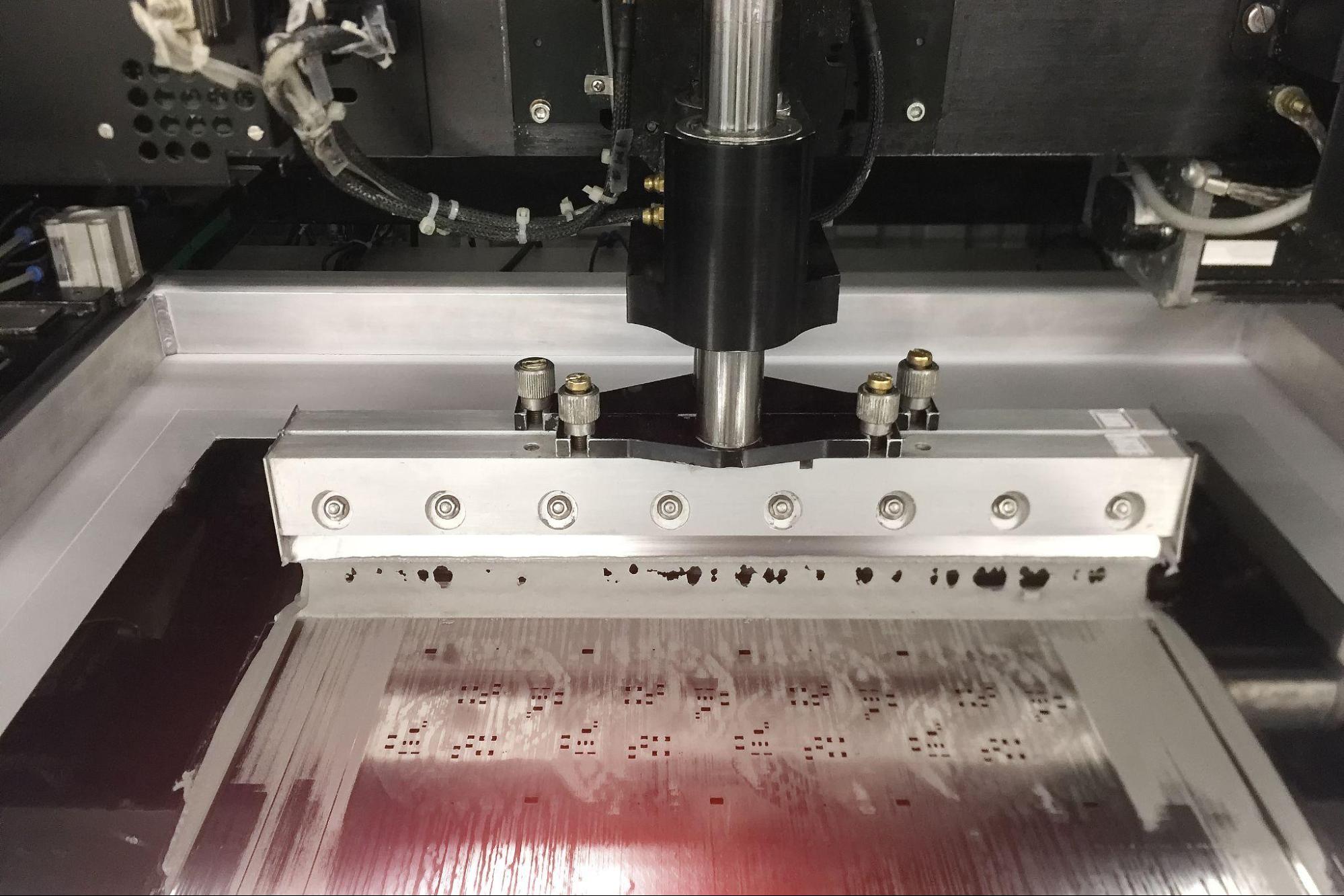
    During the PCB assembly Services process, solder paste is applied to the PCB pads using a stencil or dispensing equipment. The component leads are then placed on top of the solder paste. When the PCB is heated in a reflow oven or wave soldering machine, several key processes occur:

    • Melting: The solder paste’s solder alloy particles melt at a specific temperature, typically above the eutectic point for the chosen alloy. This temperature is lower than the melting points of the components being soldered, ensuring that the components are not damaged during soldering.
    • Wetting and Bonding: As the solder alloy melts, it wets the surfaces of the component leads and the PCB pads. The flux in the solder paste facilitates this wetting process, ensuring that the solder forms strong and reliable solder joints.
    • Solidification: Once the solder alloy cools and solidifies, it creates solid solder joints that mechanically and electrically connect the components to the PCB.

    Solder paste comes in various types, each designed to meet specific soldering requirements and manufacturing processes. The choice of solder paste type depends on factors such as the components being soldered, the assembly method, and environmental considerations. Here are some common types of solder paste:

    Lead-Based Solder Paste:

    • Lead-based solder paste contains a significant percentage of lead in the solder alloy. Common alloys include Sn63/Pb37 (63% tin, 37% lead).
    • Lead-based solder pastes were widely used in the past but have seen a decline due to environmental and health concerns associated with lead. However, they are still used in some applications where RoHS (Restriction of Hazardous Substances) compliance is not required.

    Lead-Free Solder Paste:

    • Lead-free solder paste is formulated without lead to comply with environmental regulations like RoHS.
    • Common lead-free solder alloys include Sn96.5/Ag3.0/Cu0.5 (SAC305) and Sn95.5/Ag3.8/Cu0.7 (SAC387). These alloys may contain silver (Ag), copper (Cu), and other elements.
    • Lead-free solder pastes are now the standard in many electronic manufacturing processes.

    No-Clean Solder Paste:

    • No-clean solder paste contains a type of flux that leaves minimal to no residue after soldering. This reduces the need for post-soldering cleaning.
    • No-clean pastes are commonly used when residues might be difficult to remove or when cleaning processes are not desirable.

    Water-Soluble Solder Paste:

    • Water-soluble solder paste contains flux that can be easily cleaned with water after soldering.
    • It is often used in applications where thorough residue removal is essential, such as in medical devices or military electronics.

    Rosin-Based Solder Paste:

    • Rosin-based solder paste uses flux derived from natural rosin. It is known for its excellent wetting properties and reduced spattering during soldering.
    • It can leave some residue, but it is generally considered easier to clean than traditional fluxes.

    Halide-Free Solder Paste:

    • Halide-free solder paste is formulated without halogen-containing compounds (e.g., chloride and bromide).
    • It is used in applications where the presence of halides could lead to long-term reliability issues.

    Low-Temperature Solder Paste:

    • Low-temperature solder paste contains solder alloys with lower melting points, designed to reduce the risk of heat damage to sensitive components.
    • It is used in applications where temperature-sensitive components must be soldered.

    High-Temperature Solder Paste:

    • High-temperature solder paste is designed for applications where the assembly will be subjected to elevated temperatures during its lifetime.
    • It contains solder alloys with higher melting points to ensure the solder joints remain stable.

    Specialized Solder Pastes:

    • Some applications require specialized solder pastes, such as those with enhanced thermal conductivity for power electronics or those designed for high-reliability aerospace and automotive applications.

    The choice of solder paste type should align with the specific requirements of the PCB assembly process and the end-use environment of the electronic device. Additionally, proper storage and handling of solder paste are essential to maintain its effectiveness and reliability during the assembly process.

    While solder paste may seem like a humble ingredient in the PCB assembly recipe, its significance cannot be overstated. It forms the foundation upon which reliable electronic devices are built. Choosing the right solder paste and applying it with precision are pivotal steps in the assembly process, ultimately influencing the quality, performance, and longevity of electronic products. As technology continues to advance, solder paste will evolve to meet new challenges, cementing its crucial role in the world of electronics manufacturing.

    Reach out to Epsilon Electronics for Bom optimization, Turnkey Pcb assembly, Hardware Manufacturing. We are the best PCB Assembly and Turn key solution provider in Gujarat.

    Contact Info:

    Call Us: +91 9879 6261 81
    Email: pcb@epsilonelectronics.in
    Web: www.mfg.epsilonelectronics.in

    The post The Crucial Role of Solder Paste in PCB Assembly – Why It Matters first appeared on PCB Assembly.

    ]]>
    12097
    How to Optimize your BOM for Production Activity? https://www.mfg.epsilonelectronics.in/how-to-optimize-your-bom-for-production-activity/?utm_source=rss&utm_medium=rss&utm_campaign=how-to-optimize-your-bom-for-production-activity Sat, 02 Sep 2023 10:58:13 +0000 https://www.mfg.epsilonelectronics.in/?p=11756 Bill of Materials (BOM) optimization is a

    The post How to Optimize your BOM for Production Activity? first appeared on PCB Assembly.

    ]]>

    Bill of Materials BOM Sourcing optimization is a critical strategy for electronics product manufacturers to reduce costs, improve efficiency, and maintain product quality. Here are some key steps and strategies for optimizing the BOM for electronics products:

    Component Selection and Standardization
    • Choose components that are readily available and have multiple sources to avoid supply chain disruptions.
    • Standardize on components to reduce the number of unique parts in your BOM. This can lead to bulk purchasing and better negotiation power with suppliers.
    Cost Reduction
    • Evaluate alternative components that offer similar functionality but at a lower cost. This might involve looking at different manufacturers or technologies.
    • Leverage volume discounts by consolidating component orders when possible.
    Design for Manufacturability (DFM):
    • Collaborate closely with your design and engineering teams to ensure that product designs are optimized for manufacturing processes. Minimize complex or hard-to-assemble components.
    • Consider Design for Assembly (DFA) principles to reduce the number of parts and simplify assembly.
    Lifecycle Management:
    • Monitor the lifecycle of electronic components and plan for component obsolescence. Ensure that long-term supply of critical components is secured.
    • Implement product lifecycle management (PLM) systems to track component availability and usage across multiple products.
    Value Engineering:
    • Continuously evaluate the value each component brings to the product. Remove or replace components that don’t significantly contribute to functionality or performance.
    • Consider alternative materials or manufacturing processes that could reduce costs while maintaining quality.
    Supplier Relationship Management:
    • Cultivate strong relationships with key suppliers to negotiate favorable terms, access to new technologies, and preferential pricing
    • Explore strategic partnerships with suppliers for joint cost reduction initiatives.
    Component Sourcing Strategies:
    • Use a combination of global and local suppliers to minimize lead times and shipping costs.
    • Implement just-in-time (JIT) inventory practices to reduce carrying costs and improve cash flow.
    Supply Chain Resilience:
    • Develop contingency plans for supply chain disruptions, including alternative component sources and safety stock levels.
    • Diversify suppliers to reduce dependency on a single source.
    Cost Modeling and Analysis:
    • Implement cost modeling tools and software to analyze the cost breakdown of your BOM. This can help identify cost drivers and areas for improvement.
    • Conduct regular cost-benefit analyses for potential changes in the BOM.
    Quality Assurance:
    • Maintain strict quality standards when optimizing the BOM. Reducing costs should not compromise product reliability or performance.
    • Perform thorough testing and quality control at various stages of the manufacturing process.
    Environmental Considerations:
    • Consider environmental regulations and sustainability goals when selecting components. Sustainable components may have long-term cost benefits and market advantages.
    Continuous Improvement:
    • BOM optimization is an ongoing process. Regularly review and update your BOM to incorporate new technologies, cost-saving opportunities, and market changes.

    By implementing these strategies, electronics product manufacturers can optimize their BOMs, reduce costs, enhance product quality, and improve their overall competitiveness in the market.

    Reach out to Epsilon Electronics for Bom optimization, Turnkey Pcb assembly, Hardware Manufacturing.

    Contact Info:

    Call Us: +91 9879 6261 81
    Email: pcb@epsilonelectronics.in
    Web: https://www.mfg.epsilonelectronics.in/

    The post How to Optimize your BOM for Production Activity? first appeared on PCB Assembly.

    ]]>
    11756
    PCB Assembly Service https://www.mfg.epsilonelectronics.in/pcb-assembly-service/?utm_source=rss&utm_medium=rss&utm_campaign=pcb-assembly-service Mon, 24 May 2021 15:01:16 +0000 https://demo.casethemes.net/itfirm/know-the-difference-food-delivery-apps-vs-food-copy-2/ Welcome to our comprehensive guide on PCB assembly service. If you are looking to bring your electronic designs to life, you have come to the right place.

    The post PCB Assembly Service first appeared on PCB Assembly.

    ]]>
    PCB Assembly Service: Taking Your Electronics to the Next Level

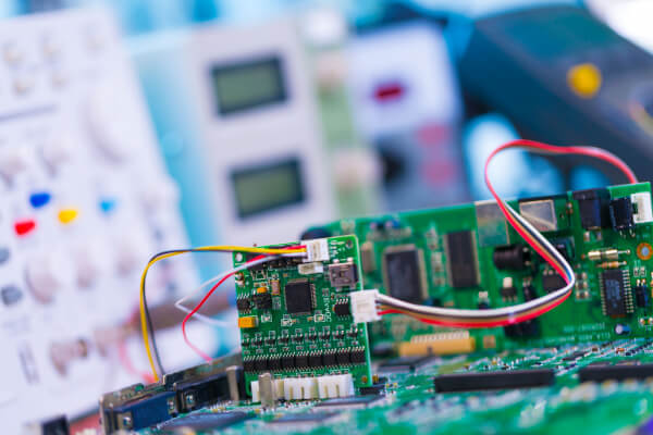
    Welcome to our comprehensive guide on PCB Assembly Services. If you are looking to bring your electronic designs to life, you have come to the right place. In this article, we will explore the ins and outs of PCB assembly and how it can benefit your projects. Whether you are a hobbyist, an entrepreneur, or a professional engineer, understanding the importance of high-quality PCB assembly is crucial for the success of your electronics ventures.

    At Epsilon Electronics, we specialize in providing top-notch PCB Assembly Services to meet the diverse needs of our clients. With our state-of-the-art facilities and experienced team, we ensure that your PCBs are assembled with precision, efficiency, and unmatched quality. Let’s delve deeper into the world of PCB assembly and discover how it can elevate your electronics to new heights.

    Why Choose Professional PCB Assembly Services?

    When it comes to assembling printed circuit boards, the quality of workmanship can make a significant difference in the performance, reliability, and longevity of your electronic devices. Opting for professional PCB Assembly Services offers a range of advantages that can save you time, money, and frustration in the long run.

    PCB Assembly Services
    Here are some compelling reasons why you should consider outsourcing your PCB assembly:
    Expertise and Experience

    Professional PCB assembly providers have the necessary knowledge, skills, and experience to handle intricate assembly processes. They are well-versed in industry best practices, ensuring that your PCBs are assembled to the highest standards.

    Quality Assurance

    Reputable assembly service providers implement stringent quality control measures to guarantee the reliability and performance of your PCBs. They use advanced testing equipment to detect and rectify any potential defects or issues, ensuring that you receive top-quality products.

    Cost and Time Savings

    Outsourcing your PCB assembly allows you to focus on your core competencies, saving you valuable time and resources. By leveraging the expertise of professionals, you can streamline your production processes, reduce wastage, and ultimately lower costs.

    Access to Advanced Technology

    Professional PCB assembly services invest in cutting-edge equipment and technologies to handle complex designs and intricate components. By partnering with a reliable assembly provider, you gain access to state-of-the-art facilities that may not be feasible to maintain in-house.

    These are just a few of the benefits of opting for professional PCB assembly services. Now, let’s explore the different types of assembly options available to meet your specific requirements.

    Types of PCB Assembly Services:
    PCB assembly services come in various forms, each catering to different project needs. Understanding these options will help you make informed decisions and choose the right assembly service for your electronics.
    Here are the main types of PCB assembly services:
    1. Through-Hole Assembly

    Through-hole assembly is a traditional method where electronic components are inserted into pre-drilled holes on the PCB and soldered on the opposite side. This assembly technique is commonly used for sturdy, low-density, and high-power applications. Through-hole assembly provides excellent mechanical strength and durability.

    2. Surface Mount Technology (SMT) Assembly

    Surface mount technology (SMT) assembly is a modern assembly method that involves soldering components directly onto the surface of the PCB. SMT assembly offers several advantages, including smaller form factors, increased component density, improved electrical performance, and lower manufacturing costs. This technique is widely used in consumer electronics, automotive applications, and other industries.

    3. Mixed Technology Assembly

    Mixed technology assembly combines both through-hole and surface mount technologies, allowing for the assembly of a wide range of components on a single PCB. This approach is often used when a combination of high-power components and miniaturized surface mount devices is required.

    4. Common Challenges in PCB Assembly

    While professional PCB assembly services provide immense value, it is essential to be aware of the common challenges that may arise during the assembly process. By understanding these challenges, you can work closely with your assembly service provider to overcome them effectively.

    Conclusion

    PCB assembly services play a pivotal role in bringing your electronic designs to life. By partnering with a professional assembly service provider, you can leverage their expertise, state-of-the-art facilities, and stringent quality control measures to produce high-quality PCBs that meet your exact specifications. Whether you are a hobbyist or a large-scale manufacturer, investing in professional PCB assembly services is a strategic decision that will enhance the performance, reliability, and success of your electronic projects.

    Contact Info
    Call Us: +91 9879 62 6181
    Email: pcb@epsilonelectronics.in
    Web: www.epsilonelectronics.in

    The post PCB Assembly Service first appeared on PCB Assembly.

    ]]>
    250